SHELLFORM TECHNOLOGIES

Structure unchanged Process reinvented

Industrializing the physical delivery workflow of cast-in-place reinforced concrete through the ShellForm™ System

Structural system and code path remain unchanged

OUR VISION
Cars and phones reach every market in the world as the same product.
Buildings cannot

A reinforced-concrete building can be replicated locally, but it cannot go global as the same product: it answers to its codes, its climate, its structural conditions, its approval path, and the chain of engineering responsibility behind it.

What repeats in every market is not the building. It is the delivery workflow behind it. Market after market, cast-in-place reinforced concrete repeats the same site work: temporary support, formwork, reinforcement placement, embedded items and MEP coordination, concrete placement and curing, stripping, insulation, plastering and finishes. That recurring delivery workflow is the true unit of industrialization for reinforced concrete.

We founded ShellForm Technologies to industrialize it: we keep the design, the code path, the approvals and responsibility chain, and the site-cast structural core local, and turn the repeatable site work behind the building into an industrialized product system that adapts to each market.

Building stays local. Delivery can be global
Transform the way the world builds
Hao (Catherine) CaiFounder & President, ShellForm Technologies Inc.
in · LinkedIn
THE SHELLFORM™ SYSTEM AT A GLANCE

We reinvent how reinforced concrete is delivered, not reinforced concrete itself.

IN THE FACTORY AND ON SITE

ShellForm™ System highlights

WHAT WE DO

A US construction-technology company, not a contractor

COMPANY

Technology, not contracting

ShellForm Technologies Inc., headquartered in the US, industrializes the delivery workflow of cast-in-place reinforced concrete, turning multi-trade site work into a product system.

DELIVERY

Deep factory integration

Non-structural, stay-in-place ShellForm™ assemblies pre-integrate reinforcement cages, connectors, insulation, conduits and boxes, the finish substrate, and, where specified, decorative finishes. The monolithic site-cast structural core and its code path remain unchanged.

PROOF

Proven across a decade

A decade of deployment in the system's market of origin, with 1,000,000+ m² of GFA delivered, backed by proprietary technology, an industry technical standard, and industry recognition.

SCALE

Built market by market

Pilot projects open each market, and production capacity is qualified through the route each market requires. Delivery runs through market-qualified capacity.

NOT PREFAB

Industrializing cast-in-place reinforced-concrete delivery, not prefab

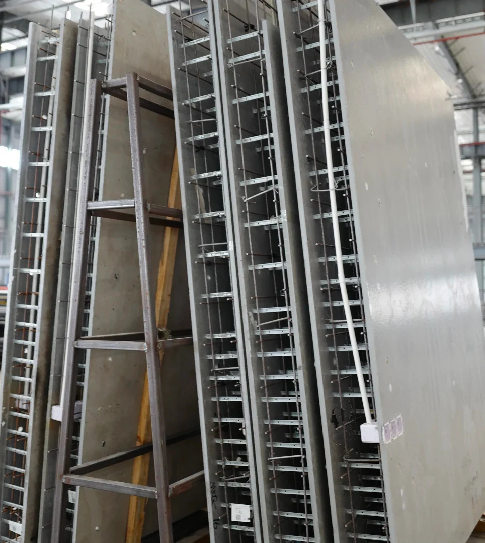
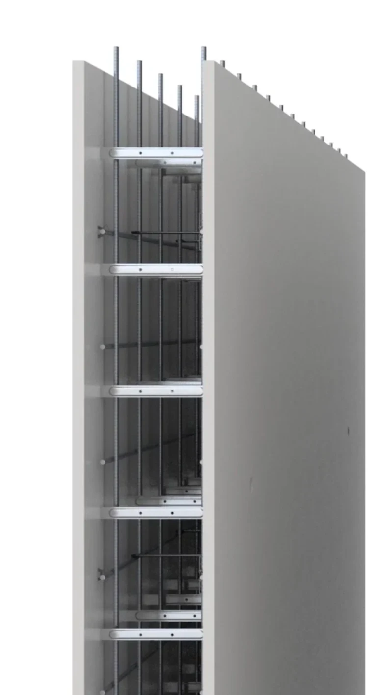
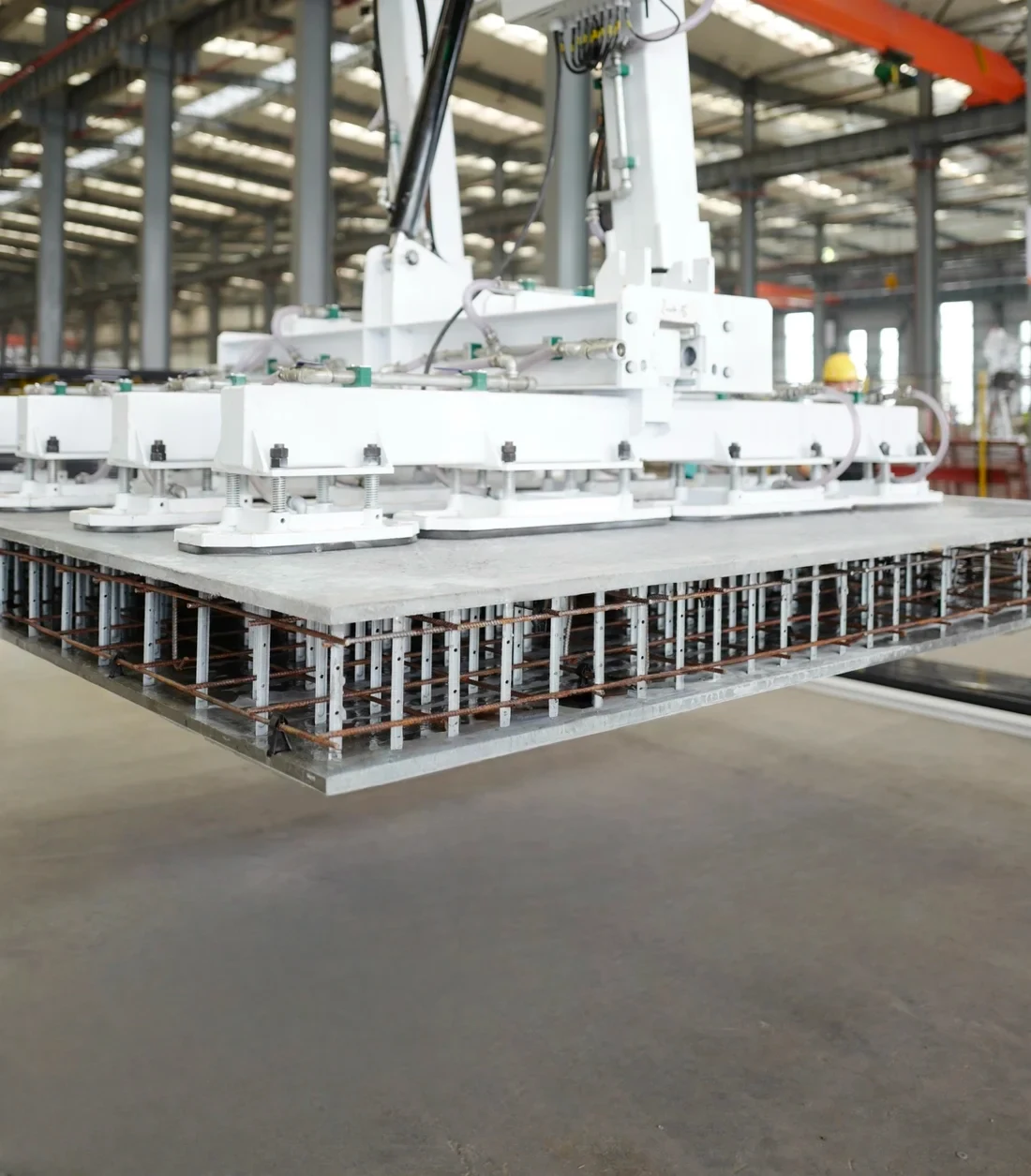
For most of the world’s cast-in-place reinforced concrete, delivery is not yet industrialized at scale: formwork, rebar, embeds, insulation, and plaster still arrive as separate trades, sequenced, coordinated, and executed largely by hand on site. The ShellForm™ System moves those repeatable trades into the factory as hollow, stay-in-place assemblies, while the load-bearing core is still cast monolithically on site.

Structural continuity between assemblies, and with conventional cast-in-place or other systems, follows the project’s structural design and applicable codes. Scope: occupied building structures such as residential, hospitality, affordable housing, and public buildings; steel and timber framing follow their own paths.

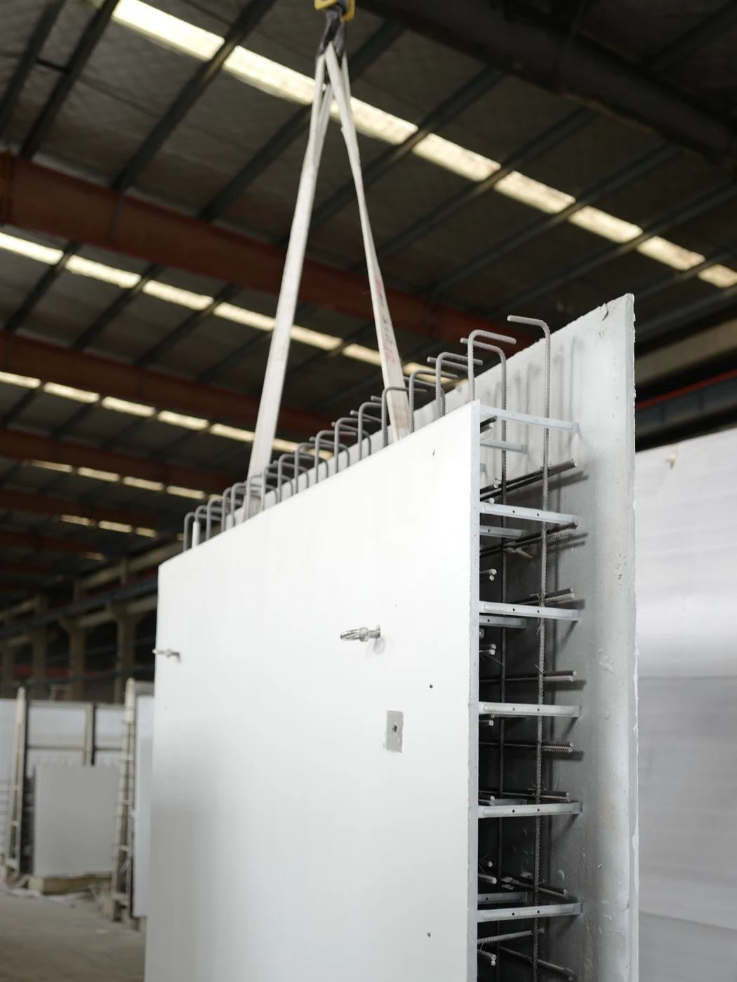
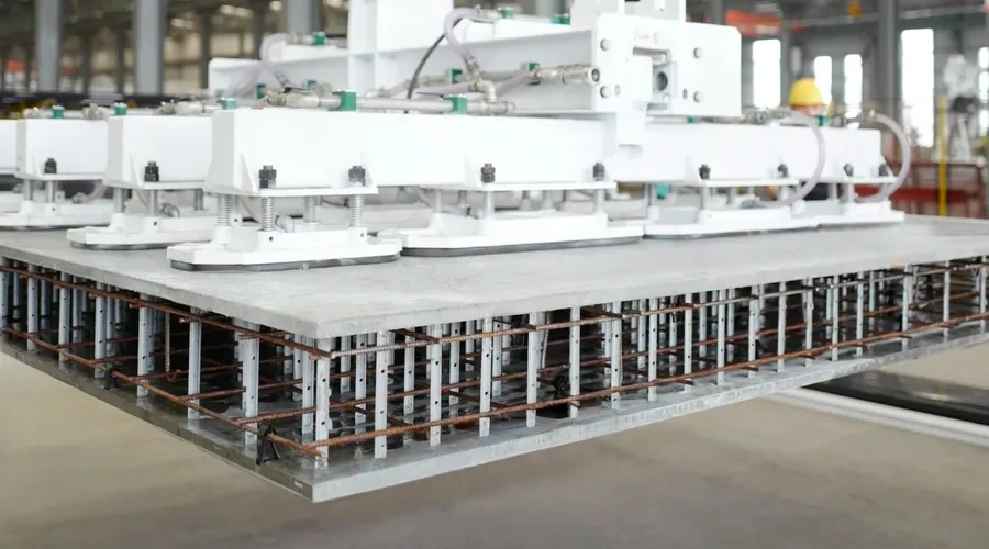
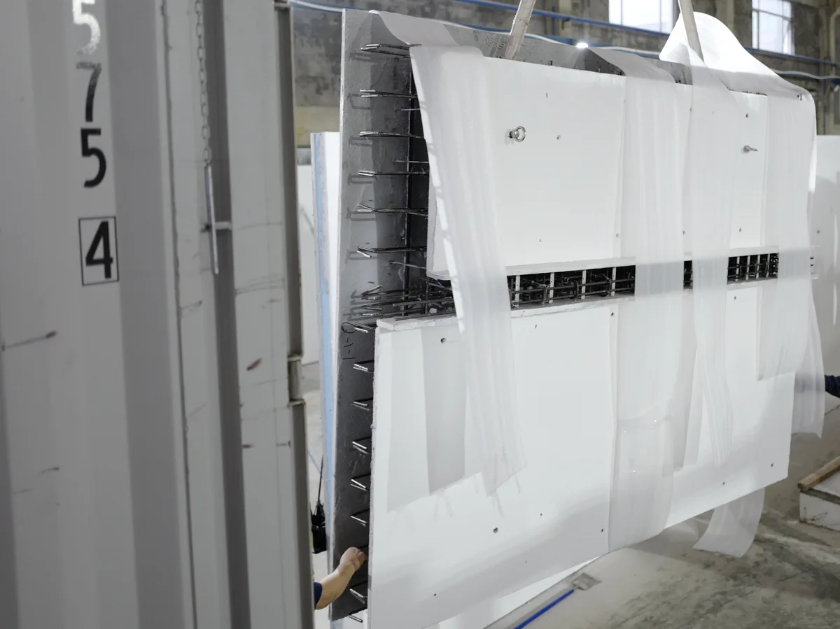
FACTORY · INSULATED T-SHAPED ASSEMBLY LIFT
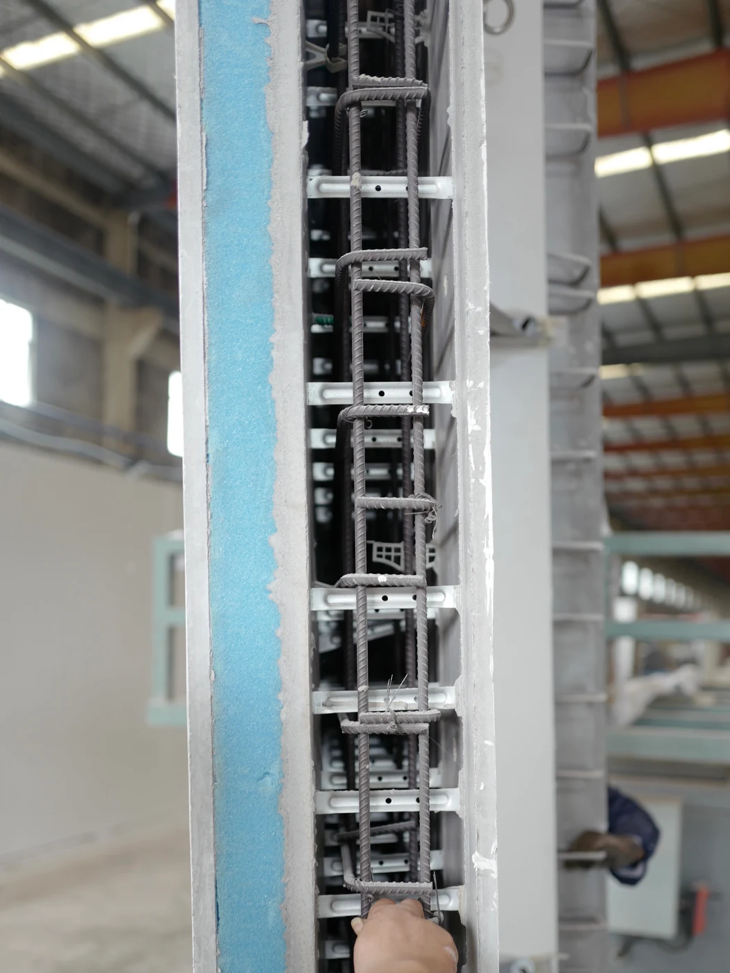
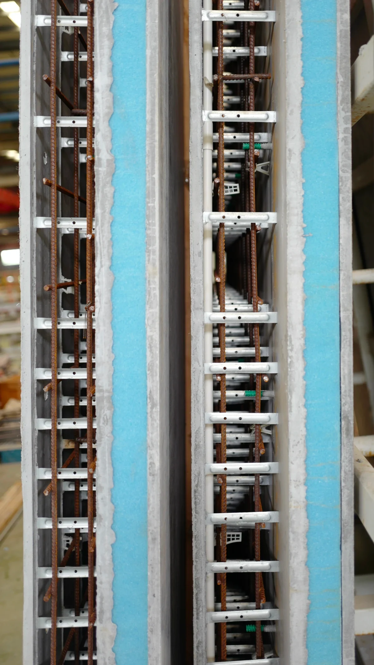
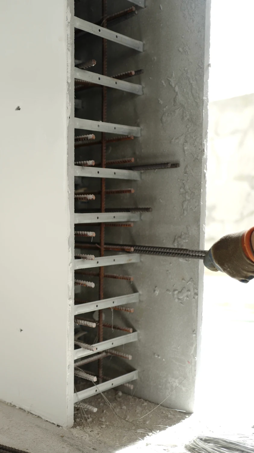
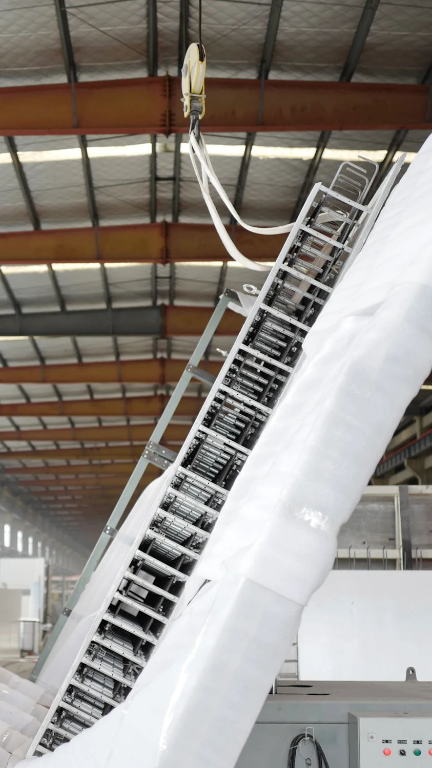
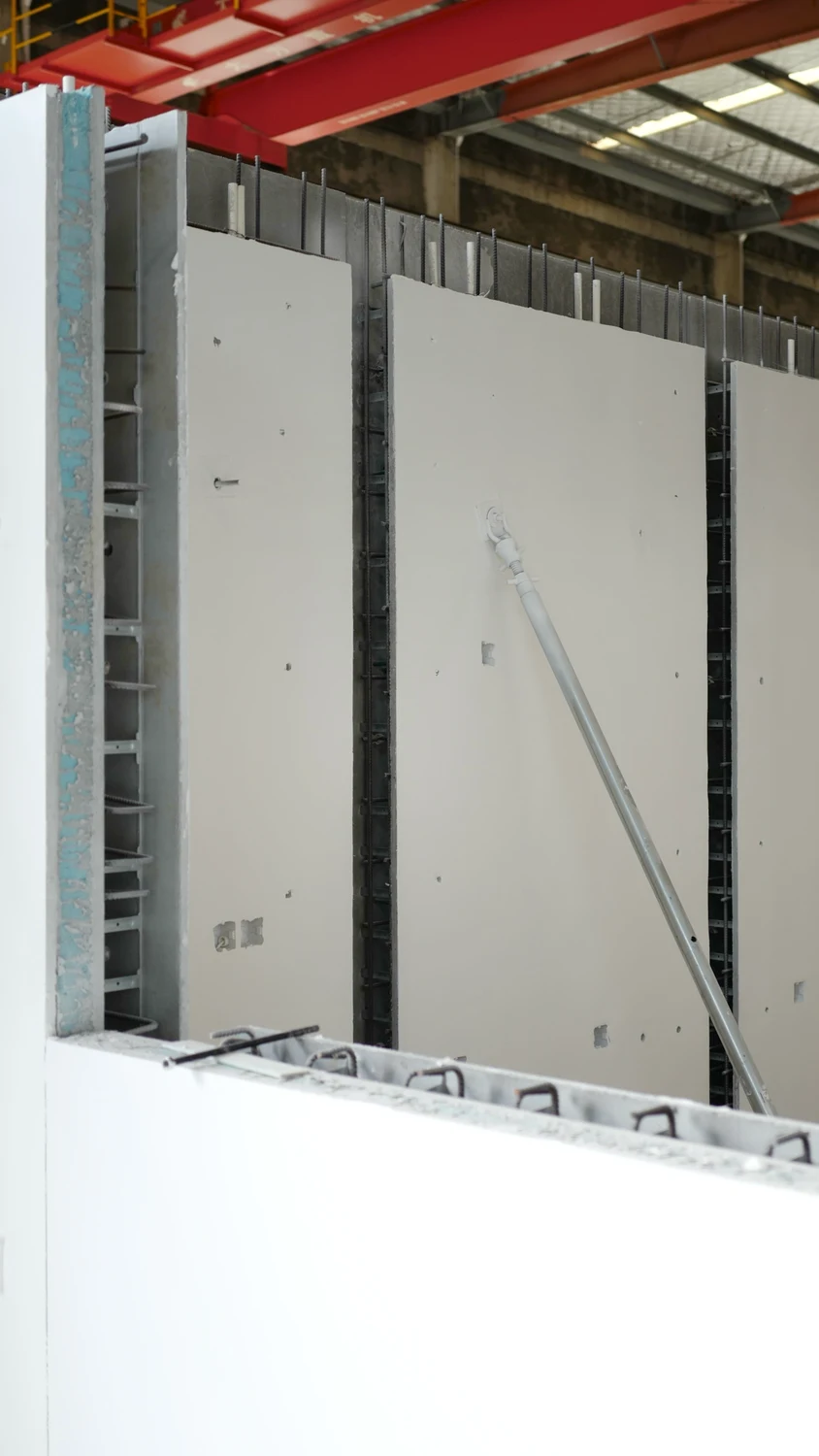
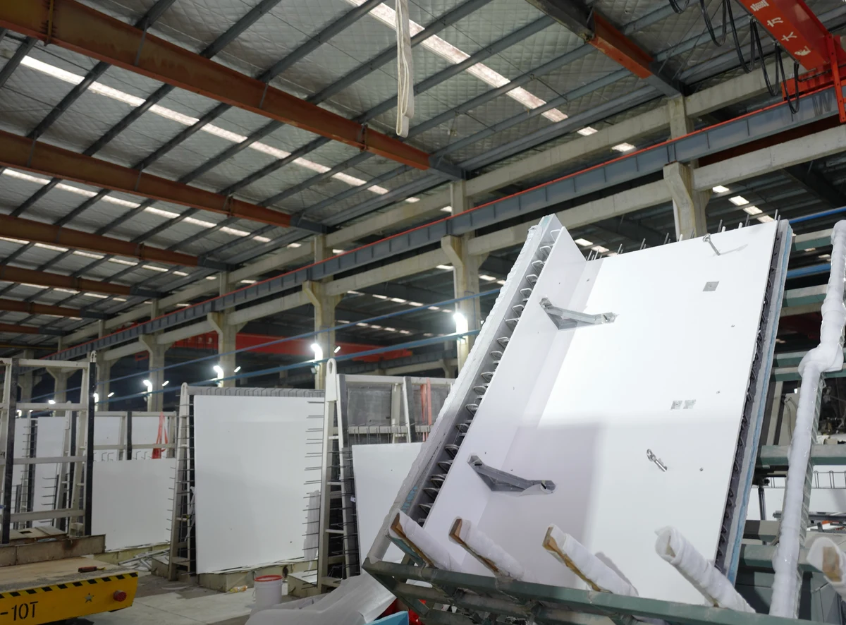
FACTORY · L-SHAPED ASSEMBLY, SIDE VIEW · BEFORE TRANSPORT TO SITE
STAY-IN-PLACE FORMWORK, TIES, REBAR, INSULATION, CONDUITS, PLASTER BASE, AND FINISH COAT ALREADY FACTORY-INTEGRATED
WHY NOW

Construction's bottleneck is field capacity, not demand

Reinforced concrete is one of the world's dominant building structures, and most of it is still cast in place on site. The delivery workflow behind it has barely industrialized while the workforce that executes it is shrinking.

The addressable market is not a share of modular or precast construction.
It is the delivery workflow of cast-in-place reinforced concrete itself, work that recurs on every project, every year.

+0%
construction labor-productivity gain 2000 to 2022, versus +90% in manufacturing
0%
of the US construction workforce set to retire by 2031
0%
of firms report difficulty hiring; workforce shortages are the leading cause of project delays
0K
net new US construction workers needed in 2026 alone
US$15T+projected global construction output by 2030, up from US$10.7T in 2020 (Oxford Economics)
Single-digitmodular construction's share of global output, even after a decade of investment (McKinsey)
Cast in placehow most of the world's reinforced concrete is still delivered, project by project

Sources: McKinsey Global Institute; NCCER; AGC of America / NCCER 2025 Workforce Survey; Associated Builders and Contractors, 2026 workforce model; Oxford Economics, Future of Construction.

It remains under-industrialized because most solutions change too little or too much

THE WORKFLOW LOCK

Isolated steps improve; the workflow stays

Digital tools, BIM, and single-task robots improve isolated steps, but the site stays a sequential, multi-trade workflow.

SHELLFORM™ RESPONSE

Moves repeatable work into the factory

Repeatable delivery operations move into industrialized factory production; site work narrows to component setting, continuity connections, and concrete placement.

THE INTEGRATION LOCK

Low-integration systems stop at formwork

Formwork and low-integration stay-in-place systems preserve the cast-in-place structure but stop at formwork or the insulation board.

SHELLFORM™ RESPONSE

Integrates beyond formwork

Factory assemblies add reinforcement integration, embeds, insulation board, and plaster and decorative finishes, moving repeatable trade content into standardized, industrialized batch production.

THE STRUCTURAL-PRODUCT AND LOGISTICS LOCK

Heavy structural products narrow the project pool

Heavy factory-made structural products narrow the project pool through weight, transport radius, lifting limits, local-code acceptance, below-grade constraints, and plant-utilization economics.

SHELLFORM™ RESPONSE

Keeps structure local and scope adaptable

Hollow ShellForm™ assemblies ship light while the load-bearing core is cast locally, allowing broader use across applicable reinforced-concrete scopes, from walls and corners to basement and foundation applications.

Sources: McKinsey (2019, 2024, 2025); Goldman Sachs (2026); Associated Builders and Contractors (2026); NCCER / Deloitte. The bottleneck in industrializing reinforced-concrete construction is not software, robotics, or factory scale alone; it is whether the repeatable work that constrains field execution can be shifted into industrialized factory production without turning the structure itself into a factory product.

WHAT SHELLFORM IS, AND WHAT IT IS NOT

An integrated construction system, on the conventional code path

COMMONLY ASSUMED

A prefab, modular, or formwork-only product

WHAT IT ACTUALLY IS

An integrated ShellForm™ construction system

Repeatable site work moves into factory-integrated stay-in-place ShellForm™ assemblies, while the reinforced-concrete structural core remains site-cast and monolithic.

COMMONLY ASSUMED

A contractor or panel supplier

WHAT IT ACTUALLY IS

A construction-technology company

ShellForm Technologies provides the system, proprietary materials, assembly fixtures, equipment specifications, software, and partner services.

COMMONLY ASSUMED

A niche partial solution or whole-building replacement

WHAT IT ACTUALLY IS

Flexible deployment scope

Deployed selectively or broadly across applicable reinforced-concrete scopes, without changing or replacing the whole-building structural system.

ONE SYSTEM, ONE COMPANY

Invented at production scale. Structured for global markets

The ShellForm™ System carries a decade of delivery behind it. ShellForm Technologies Inc. was established in 2026 as the global technology company that owns the system's international brand and IP, holds its certifications, and carries it into new markets as sole applicant and designated report holder.

TECHNOLOGY ORIGIN AND SUPPLY

Invented and validated at scale

A decade of field deployment in the system's market of origin, one of the world's largest construction markets, with 1,000,000+ m² of delivered GFA and the governing industry technical standard co-authored in 2018.

Supply base to the international platform
Proprietary cementitious composites, connectors, and assembly fixtures supplied from the established production base while regional capacity qualifies
INTERNATIONAL COMMERCIALIZATION AND IP

ShellForm Technologies Inc. · Delaware, USA

Brand, trademark, and IP
International brand rights, trademark, and new IP filings held by the US entity for global markets
Certifications and market approvals
Sole applicant and designated holder across all pathways; factories are qualified locations under them
Future technology roadmap
Product development and the technology roadmap, directed by the US entity
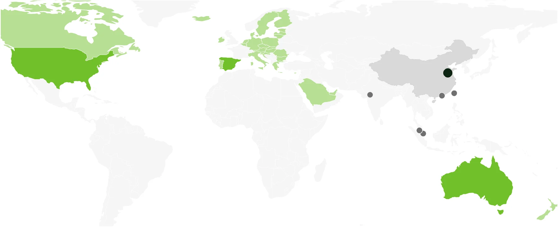
ShellForm target markets world map

Underway: certifications and first pilot

US and Australia: certification evaluation in progress · Europe: first international pilot shipped, in transit by sea

Extension markets

Extension markets follow additional ICC-ES country code reports and the EU-wide ETA on the same evaluated technical basis

Separate strategic-market pathways

Singapore, Malaysia, Hong Kong, Taiwan, and India through market-specific routes

United StatesAustraliaEurope CanadaNew ZealandSaudi ArabiaUAEIndiaMalaysiaSingapore
THE SHELLFORM™ ASSEMBLY

Factory-integrated layers. Site-cast structural core

1Interior PanelF

Cementitious composite, ≈ 20 mm; stay-in-place; finish substrate

2Conduits & BoxesF

Factory pre-installed MEP coordination

3Rebar SpacersF

Maintain concrete cover; cast into the wet panel

4Reinforcement CageF

Conventional cast-in-place rebar; pre-installed per structural design

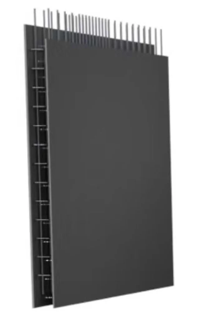
Exploded view of the ShellForm assembly

5Galvanized Steel ConnectorsF

Maintain cavity geometry; not part of the final structural load path

6Insulation ConnectorsF

Retain insulation; locked in the cast-in-place concrete core

7Exterior PanelF

Cementitious composite, ≈ 20 mm; stay-in-place; exterior finish substrate

8Insulation BoardF

XPS or per project requirements

9Protective LayerF

Cementitious, 12 to 20 mm; shields insulation

10SITE-CAST STRUCTURAL CONCRETE · S
Structural concrete fills the cavity on site and forms the monolithic reinforced-concrete core. The final load path is the reinforcement cage plus site-cast concrete, and nothing else; all other factory-integrated components are non-structural delivery-layer components.
F  Factory-integrated / pre-installedS  Site-cast operation●  Final structural load path
THE SHELLFORM™ ASSEMBLY · THE LOAD PATH

The product is not the structure

Highlighted in the model: the cementitious composite panels and the galvanized steel connectors. Both are excluded from the structural calculation and carry no structural load. The reinforcement cage arrives factory pre-installed; the load is carried by the cage and the structural concrete, cast entirely on site, forming one monolithic structure.

FACTORY-INTEGRATED SCOPE
1. Cementitious composite panels
Cementitious composite, ≈ 20 mm; serves as formwork, then stays as the plaster and finish substrate; non-load-bearing
AS DESIGNED, AS BUILT

The assembled model, and the factory-produced unit

FACTORY-INTEGRATED TRADES
  • Formwork
  • Form ties
  • Rebar cage
  • Conduits & boxes
  • Insulation board
  • Plaster & decorative finishes
Factory-produced ShellForm units with QR labelsFactory-produced unit, panel face and connectorsFactory-produced unit ready for dispatch
Factory production: each unit carries a QR label linking it to its material batches and QA records; insulation and factory-applied finishes are configured per project
THE MEMBER FAMILY

Shear walls, columns, beams, slabs,
and partitions in one system

ShellForm™ assemblies cover conventional cast-in-place reinforced-concrete structural systems, including shear wall, frame-shear wall, and frame-core tube configurations. Member geometries shown are representative;
final assemblies are configured to the project structural design.

THE MEMBER FAMILY · POSITION IN THE STRUCTURE, MEMBER BY MEMBER
Straight shear wall

Straight shear wall

The core hollow stay-in-place wall assembly: interior and exterior cementitious composite panels, galvanized steel connectors, a pre-positioned reinforcement cage, and an open cavity for on-site structural concrete placement.

BELOW GRADE

The schedule advantage starts below grade

The same wall and column assemblies extend directly into foundations: strip footings, isolated footings, and continuous basement walls, from villas to commercial and industrial buildings.

Foundation configuration with wall and column assemblies
Column assemblypre-installed reinforcement cage
Wall assembly, second stepstay-in-place
Wall assembly, first stepstay-in-place
Reinforcement matfield-placed

Application scope

Large isolated footings, strip footings, and continuous basement walls; most valuable where excavation faces require vertical formwork, shoring, reinforcement tying, or column-base integration.

Monolithic continuous placement

Wall and column-base assemblies are positioned together; wall panels carry graded flow openings so concrete can flow into the connected cavities and fill them uniformly.

Lighter than solid precast

Hollow factory-made shells weigh a fraction of solid precast foundation units, easing transport, lifting, and installation; the footing is completed as one cast-in-place pour, without heavy precast-to-precast connections.

Schedule from the foundation up

Reduces scaffolding and on-site formwork setup along excavation faces, so the schedule benefit begins at the foundation and carries through the project.

Example configuration shown: a 4.0 × 4.0 m footing, 0.5 m deep, supporting an 840 mm column; dimensions are project-determined, not a system limit. Factory-produced cementitious composite panel faces and galvanized steel connectors are non-structural; the load path is the field-placed reinforcement plus site-cast concrete.

THERMAL, FINISH & FAÇADE MODULES

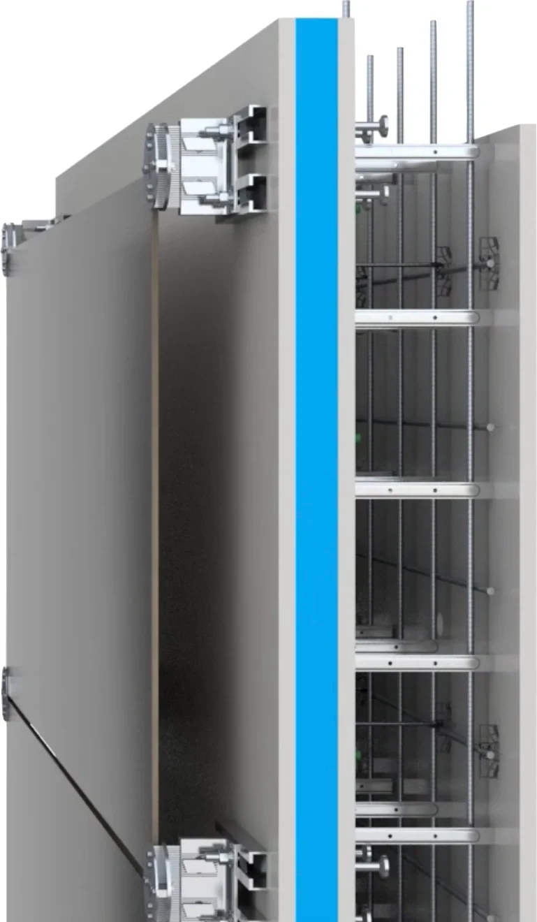
Base assembly with optional thermal, finish, and façade-interface modules

Shown on a wall assembly as the illustrative case; the same thermal, finish, and façade-interface modules apply across the member family, configured to each project.

MODULE CONFIGURATIONS COMPARED · SHOWN ON A WALL ASSEMBLY

Modules are selected by requirements; the site-cast reinforced-concrete structural core remains unchanged.

1 · BASE ASSEMBLY

The core hollow stay-in-place unit

Shown as a wall: interior and exterior cementitious composite panels, galvanized steel connectors, a pre-positioned reinforcement cage, an open cavity for the structural pour, and embedded conduits and boxes where required.

Base wall assembly
+ · THERMAL MODULE

Insulation anchored by concrete, not adhesive

Full-length insulation connectors are set into the still-wet panels on both sides of the board and extend into the structural cavity, encased by the site-cast concrete. This concrete encasement greatly reduces the debonding risk of conventional external insulation.

Thermal module
+ · FINISH / FAÇADE MODULE

Factory-integrated finish paths

Factory coating or paint, textured formliner, reverse-cast veneer in tile, stone, brick, or porcelain, and embedded façade or PV inserts, all integrated during factory panel production or at a factory finishing station.

Finish module
PANEL THICKNESS

20 mm standard in current deployments; oversized members can be upsized to 25 mm or more where needed; 12 mm validated in controlled testing, deployment pending

CAVITY THICKNESS

Equals the structural wall thickness per design; the cavity is the cast-in-place structural core

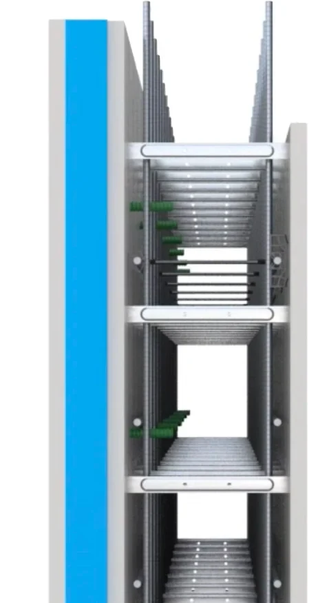
The insulated cavity in detail: assembly model with full-length insulation connectors extending into the structural cavity. The rebar spacers shown are cast into the wet panel and maintain concrete cover.
Insulated cavity, factory unit
The same detail in the factory-produced unit: connectors, insulation, conduits, and reinforcement before the structural pour
PROPRIETARY MATERIALS · 01 · STAY-IN-PLACE PANEL FACES

One proprietary material, two jobs:
permanent formwork, then finish substrate

The proprietary cementitious composite panel resists the fresh-concrete pour, stays permanently in place as the plaster and finish base, and carries no structural load. This dual role is the core of the ShellForm™ System.

20 mm standard in current deployments
12 mm validated in controlled testing, deployment pending

Dual function, non-structural by design

Non-structural stay-in-place panel faces resist fresh-concrete lateral pressure during the on-site structural pour, then stay permanently in place as the plaster and finish substrate; the panels are excluded from the structural calculation.

Performance

Supports on-site pours up to 6 m, placed in conventional lifts. Panels and galvanized steel connectors form an integrated system; panel thickness and connector spacing tune to the design pour.

Sustainability

The formulation incorporates 50 to 70% low-carbon constituents, and the permanent panels remove the need for separate reusable timber or aluminum formwork, cutting on-site material cycling and waste.

Raw material supply

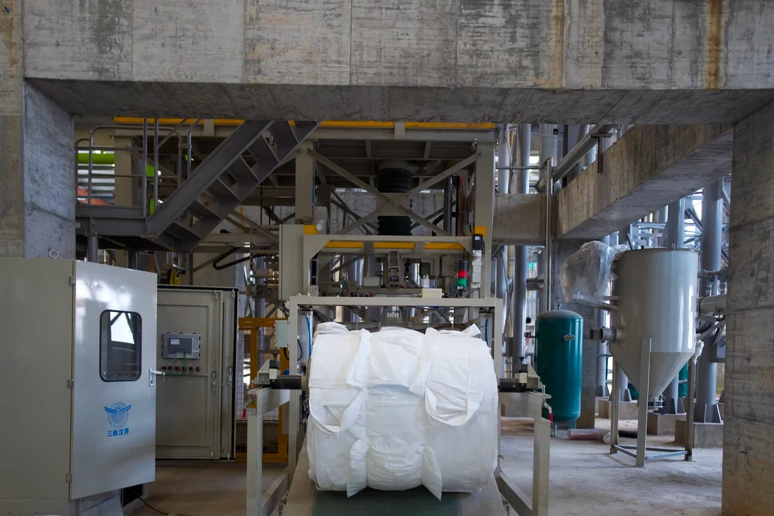
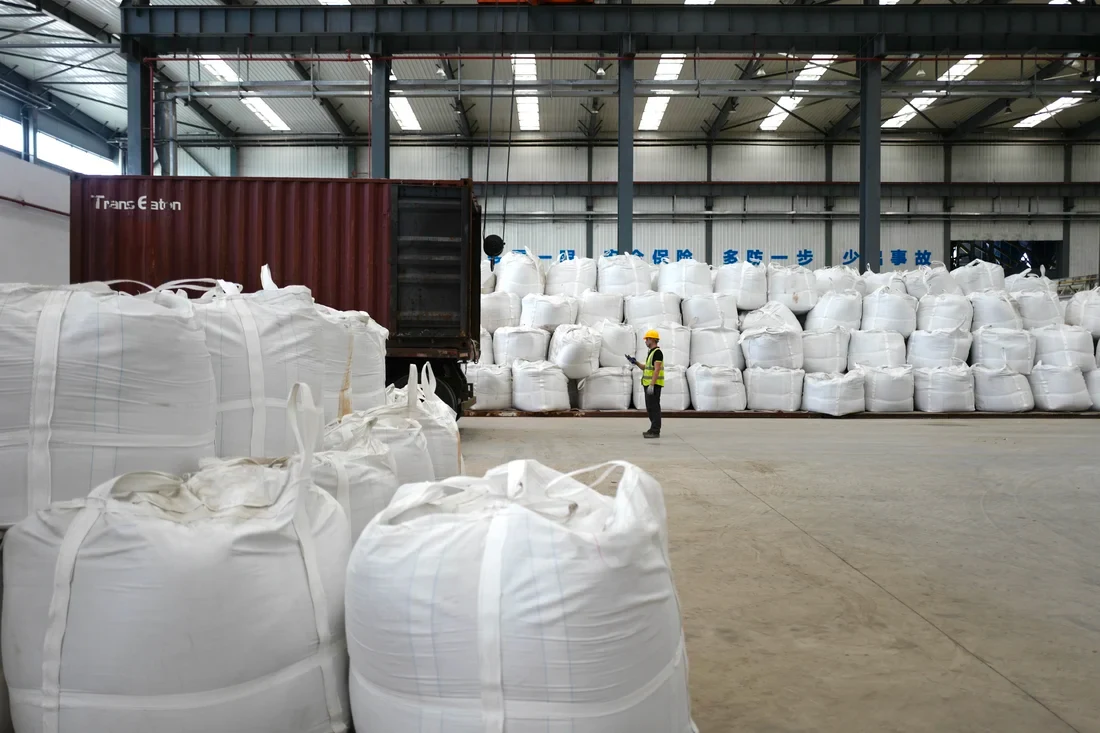
In-house automated production of the proprietary cementitious composite dry mix, pre-batched to specification and supplied in 1.5-tonne bulk bags, with an installed design capacity of 1,200 tonnes per day; fibers and admixtures are supplied separately and dosed at mixing, when the dry mix is combined with water at the assembly facility.

RAW MATERIALS · DRY-MIX PRODUCTION LINE
Dry mix production line
Dedicated in-house fully automated dry mix production line
Dry mix packaging line
Bulk bags at assembly facility
Bulk bags received at the assembly production facility
PROPRIETARY MATERIALS · 02 · CONNECTORS

Proprietary galvanized steel connectors tie
the panel faces and maintain cavity geometry

Thin strip geometry

Each connector is a thin, flat galvanized steel strip. Its length matches the cavity dimension of each specific assembly, and lengths range across the product family to accommodate all member types.

On-edge orientation

Each connector spans panel face to panel face, standing vertically on its thin edge, in the same plane as the transverse reinforcement, so concrete placement and vibrator consolidation are not obstructed.

Pressure-based spacing

Spacing is denser in the lower zone of each member to resist higher fresh-concrete lateral pressure; standard spacing applies in the upper zone, set per the structural design and quality-control program.

Independent of reinforcement

Connectors tie the panel faces only and make no contact with the reinforcement cage, which is positioned independently by plastic rebar spacers embedded during factory panel production.

FACTORY PRODUCTION

Single-cure wet-state co-casting on one production line

A proprietary reconfigurable assembly fixture integrates the reinforcement cage, connectors, electrical boxes, insulation board, embeds, and optional modules, so both panel faces and the integrated cage form in one wet-state sequence before a single factory cure.

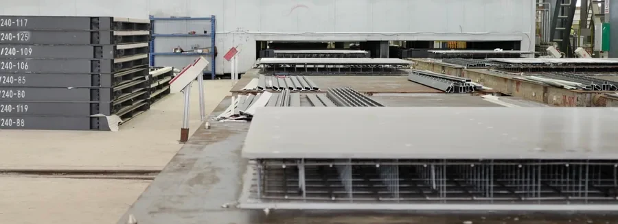
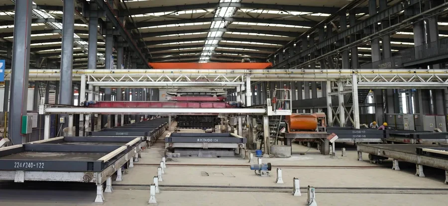
Mold-table system: fixed or traveling mold tables

Reconfigurable production platform

Adjusts height, width, cavity depth, and panel thickness for project-specific assemblies, without fixed molds.

Highly-integrated assembly fixture

Reinforcement cage, galvanized steel connectors, embeds, and optional modules, highly integrated in the offline-preloaded assembly fixture.

First panel face

Cast on the mold table.

Preloaded assembly fixture

The offline-preloaded assembly fixture, carrying the reinforcement cage, connectors, and embeds, is positioned onto the wet first panel.

Insulation, where specified

For insulated assemblies, the insulation board and full-length insulation connectors are placed after the first face, set into the still-wet panel.

Second panel face

Cast onto the assembly fixture, completing both faces in one wet-state sequence.

Single factory cure

One cure cycle for the whole assembly; no flipping.

Demold and transfer

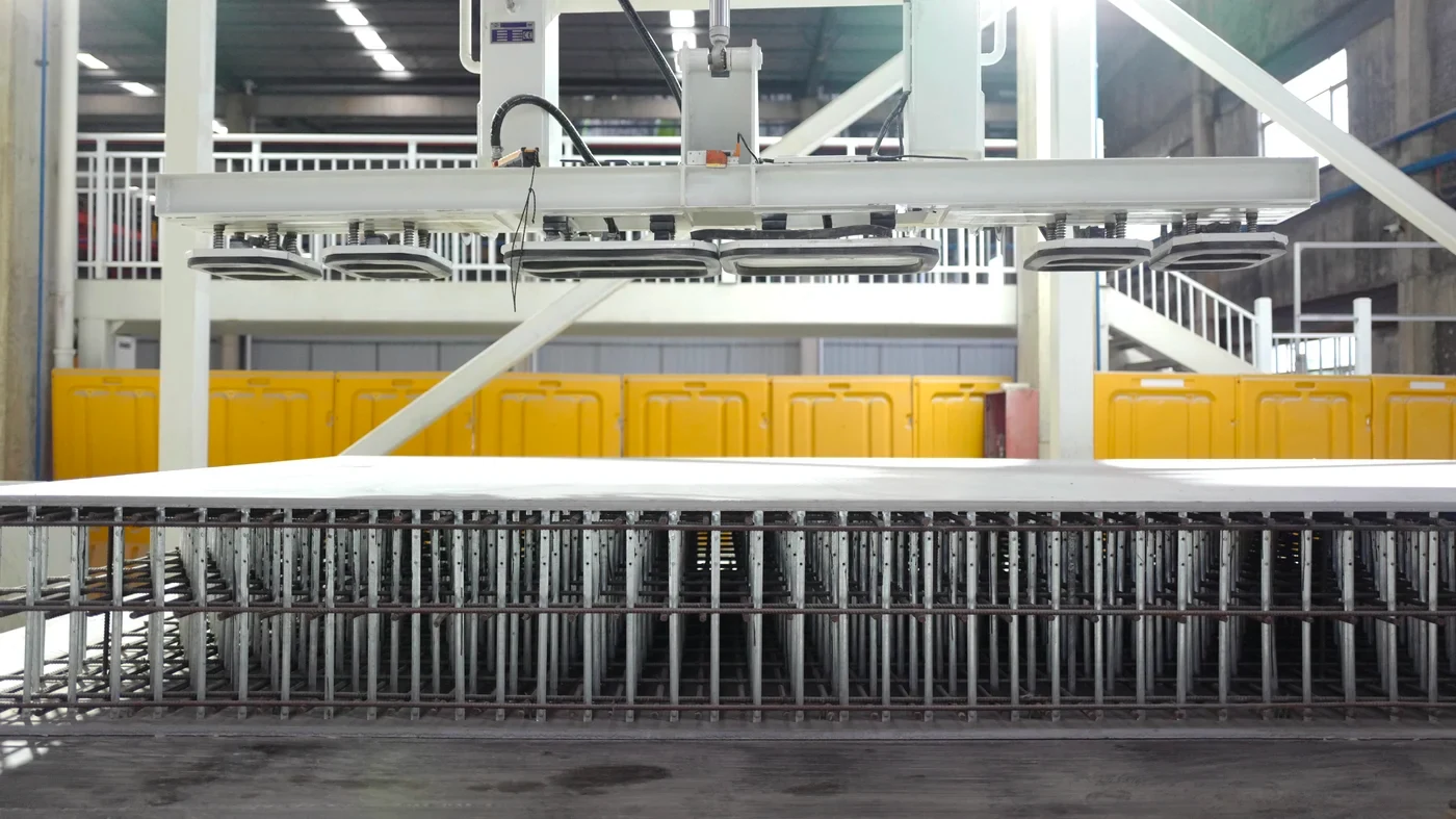
Vacuum-lifter demolding; the assembly fixture and mold table return to the cycle.

Single cure, no flip applies to straight assemblies. L- and T-shaped members, beams, and columns use the same assembly fixture-based wet-state forming principle, formed in stages on the same production line.
SOLID PRECAST

Fixed molds, member by member

One size per dedicated mold; cast a solid load-bearing member, steam cure, demold.

1 cure cycle · 8 to 12 h · one member per mold
HOLLOW DOUBLE-WALL

Two casts, two cures, one flip

Cast and cure the first shell, cast the second, turn the first 180° onto it, then cure both.

2 cure cycles · 8 to 12 h each · one 180° flip
SHELLFORM™ SYSTEM

One wet-state sequence, one cure, no flip

Both panel faces and the integrated cage form in one sequence on the highly-integrated assembly fixture.

1 cure cycle · 8 to 12 h · no flip · reconfigurable assembly fixture, no dedicated molds
THE DIFFERENCE

The product is not the structure

In solid precast and double-wall, the precast members are themselves load-bearing; in the ShellForm™ System the panels, connectors, and embeds are excluded from the structural calculation; the load is carried by the reinforcement cage and the site-cast structural concrete, forming one monolithic structure.

Cure-cycle figures compare straight shear-wall production.

CURE CYCLES PER MEMBER · FACTORY ROUTES COMPARED · STRAIGHT SHEAR WALLS
Solid precast wall
1 cure · 8 to 12 h · dedicated mold per member
Hollow double-wall panel
2 cures · 8 to 12 h each · one flip between
ShellForm™ wall assembly
1 cure · 8 to 12 h · no flip · no dedicated molds
Vacuum lifter engaging the assembly on the mold table
On the mold table: suction pads engage the cured assembly evenly across its face
Vacuum demolding, assembly leaving the mold table
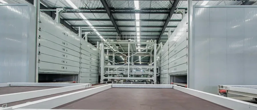
Demolding: the assembly leaves the mold table for the A-frame rack
BEAMS, COLUMNS, AND L/T MEMBERS FORMED ON ONE LINE

L- and T-shaped members use the same assembly fixture-based wet-state principle, formed in stages on the same line.

IN THE FACTORY · UP CLOSE · BEFORE SHIPMENT

Up close

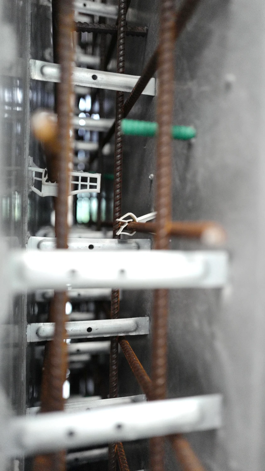
Rebar spacers holding the cage at concrete cover

Held at cover. Rebar spacers, cast into the wet panel, hold the pre-positioned cage at its specified concrete cover. The cage and the galvanized steel connectors are separate systems: the connectors tie the panel faces and maintain cavity geometry, with no contact with the rebar.

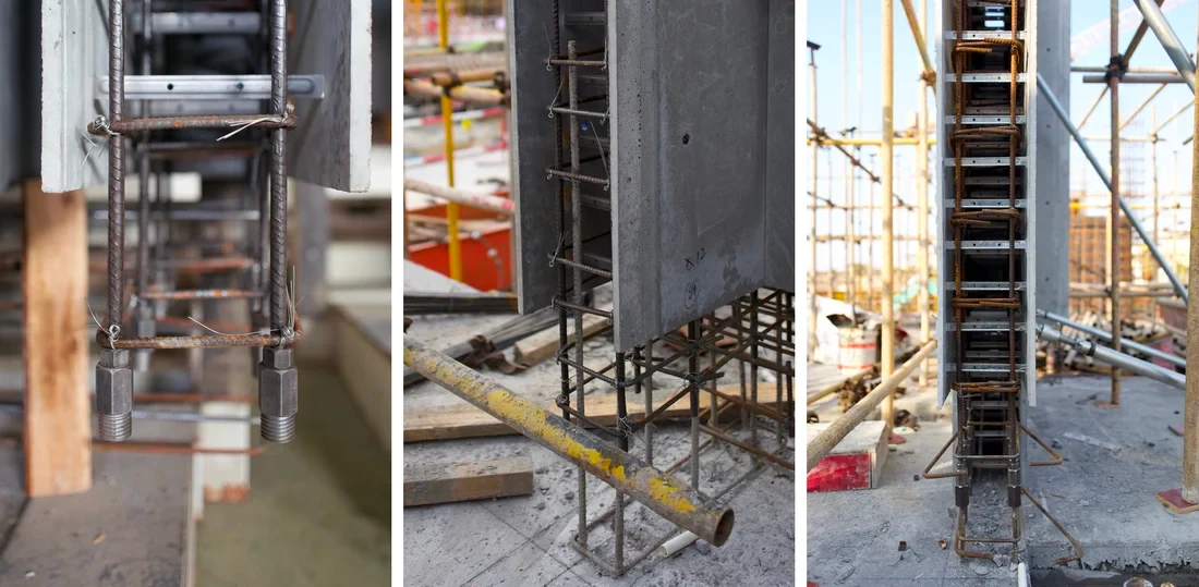
Horizontal connection bars wire-tied in the factory

Placed to pull out. Horizontal connection bars are laid in and wire-tied at the factory; on site, once members are erected, the bars draw out to lap with the adjacent member.

Oversize assembly on the assembly upender

Turned by the upender. An oversize assembly is repositioned on the assembly upender ahead of transport; connector spacing and the internal build-up read clearly in section.

Laser rust removal on projecting bars

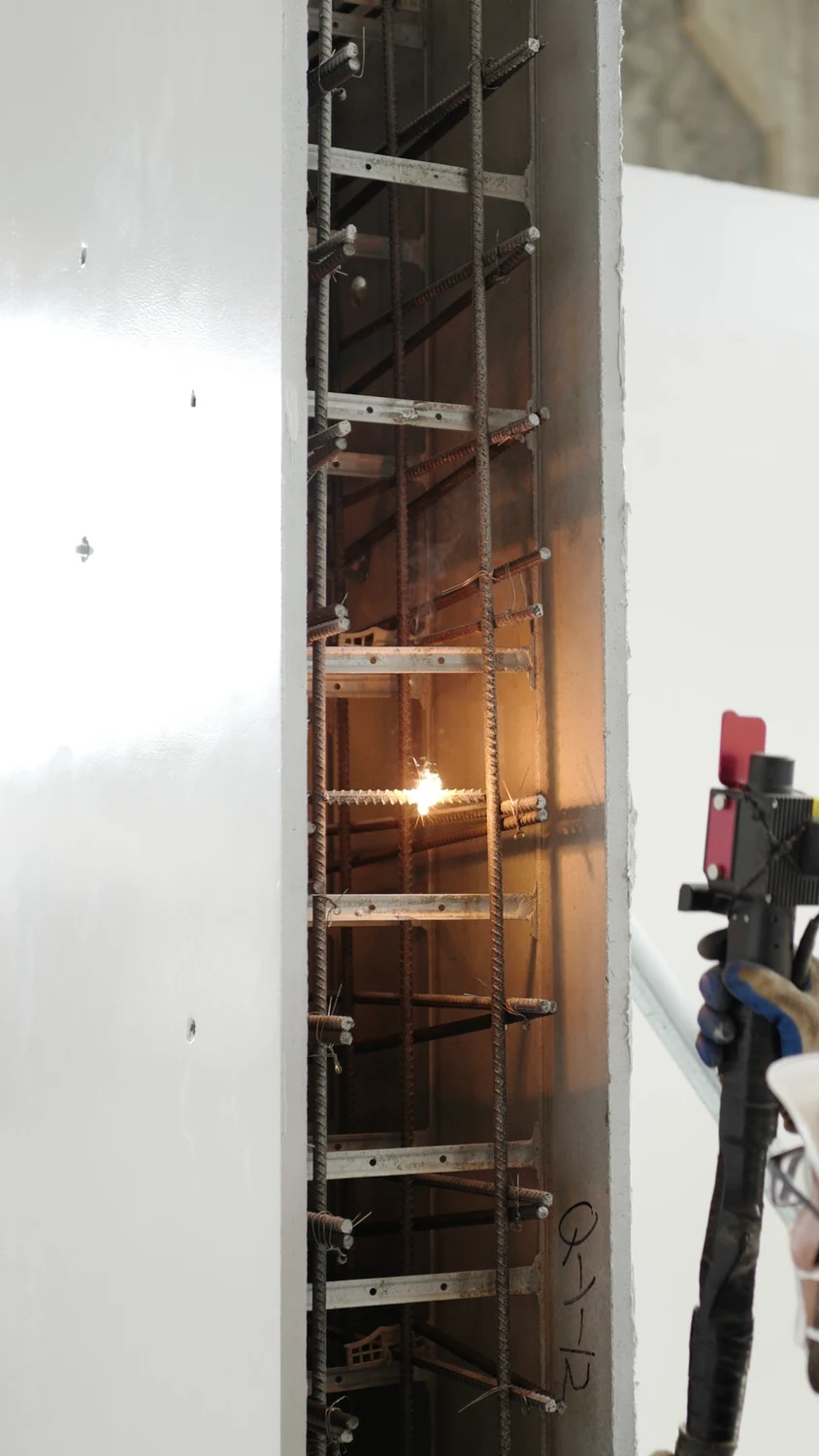
Clean steel for the voyage. Laser rust removal on the projecting bars before container packing for sea freight.

Factory trial assembly before an overseas shipment

A rehearsal, not a production step. Factory trial assembly ahead of an overseas shipment: tight butt joints on the outer face, hand-hole access on the inner face for the rebar connections, with fixing holes alongside for the hand-hole closures. Carried out for the first overseas shipment, verifying fit and tolerances before dispatch.

PRODUCTION LINE SETUP

ShellForm™ System scope of supply, packaged for greenfield or retrofit lines

PROPRIETARY EQUIPMENT
LEASED FROM SHELLFORM
  • Wall assembly fixtures
  • Column and beam assembly fixtures
PURCHASED FROM SHELLFORM
  • Vacuum demolding lifter
  • Site assembly upender · under transport restrictions, repositions oversized assemblies for lifting
PROPRIETARY MATERIALS AND ACCESSORIES
PROCURED THROUGH SHELLFORM
  • Cementitious composite material package
  • Galvanized steel connectors
  • Rebar-cage positioning spacers
  • Electrical boxes
  • Insulation ties, where applicable
PRODUCTION LINE SYSTEMS
  • Mixing system · dedicated mixer, bulk-bag opener, tube-chain conveyor, control system
  • Distribution system · flying bucket and concrete spreader
  • Mold-table system · fixed or traveling mold tables
  • Rebar fabrication system · mesh welding, mesh bending, stirrup bending, butt-welding
  • Curing system · curing chamber or spray-curing system
  • Auxiliary equipment · A-frame racks, adjustable braces, dedicated cutting machine
EXISTING PLANT RETROFIT

Assess retain upgrade or supplement

  • Equipment assessed against ShellForm requirements; qualifying systems retained
  • Systems short of ShellForm specifications upgraded or supplemented
  • Remaining gaps procured through ShellForm or sourced to ShellForm specifications
  • Retrofit and upgrade investment remains with the partner
GREENFIELD FACILITY

Design configure commission

  • ShellForm designs and supplies the complete production line
  • Proprietary assembly fixtures leased from ShellForm Technologies
  • ShellForm provides installation, commissioning, and acceptance support
  • Factory building, working capital, and other supporting facilities remain with the partner

Partner and local scope by design: ordinary reinforcement, ready-mix structural concrete, and commodity materials are sourced locally.

0
casting tables in a fixed mold-table reference deployment
0
standard assembly fixtures, ≈ 100 assemblies per day
0
annual output at the upper end of the reference range, ≈ 240,000 m² of single-face shear wall
0
operating days per year, reference schedule

Production lines may be configured as fixed or traveling mold-table systems and may run single or mixed assembly types, with the highest throughput achieved when focused on a single product family; actual output depends on facility layout, product mix, shifts, utilization, and market demand. Figures are calculated from a fixed mold-table reference deployment optimized for shear wall production under a 300-day reference operating schedule, with each assembly estimated at 1.8 m³ (2.5 m wide × 3 m high × 0.24 m thick).

Production line
Production line
Production line
Production line
LOGISTICS · FROM FACTORY TO SITE

Lightness makes distance economical. The unchanged structure makes it possible

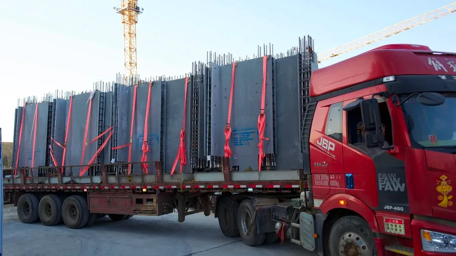
Hollow assemblies ship before concrete is placed, so structural scope moves on standard trucks and standard cranes rather than oversize logistics.

A fraction of solid weight

A typical 3 × 3 × 0.2 m wall assembly weighs under 1 tonne, roughly one-fifth to one-sixth of an equivalent solid element; a standard light-duty crane handles it.

Road radius 500 to 1,000 km

The economical road radius runs roughly 500 to 1,000 km [300 to 600 mi] from the production facility, several times that of solid precast; delivered projects have shipped roughly 800 to 1,300 km by road.

Travels across markets by design

Because the structural design and code path stay conventional cast-in-place, distance does not break compliance: reinforcement is integrated to the project’s structural design under the local code, insulation and finishes follow the design’s own specification, and only the concrete is placed on site. Long reach also concentrates production: one qualified base can serve many markets before local capacity is justified.

Sea freight beyond

For overseas delivery, assemblies load into standard open-top containers at the factory; the first European pilot project shipped this way, roughly 16,000 km from the production base.

SITE INSTALLATION

Conventional in structure. Industrialized in process

CONVENTIONAL STRUCTURE

Rebar is connected by conventional lap splicing or mechanical couplers per project structural design and applicable code, and structural concrete is placed per design. The finished reinforced-concrete core is monolithic cast-in-place, indistinguishable from conventional RC construction.

INTEGRATED CONSTRUCTION PROCESS

Formwork, form ties, plastering, insulation, MEP embedment, and decorative finishes where specified are already in place when the assembly arrives. Fewer site trades translate to shorter schedule, reduced site overheads, and less construction waste; the same crews deliver more project throughput.

LIGHT SITE FOOTPRINT

A typical 3 × 3 × 0.2 m shear wall assembly weighs under 1 tonne, roughly one-fifth to one-sixth of an equivalent solid wall. A standard light-duty crane and a 3-person crew can handle installation in typical site conditions.

1 · Transport

Light hollow assemblies arrive by standard truck; no oversize logistics or special permits.

2 · Layout marking

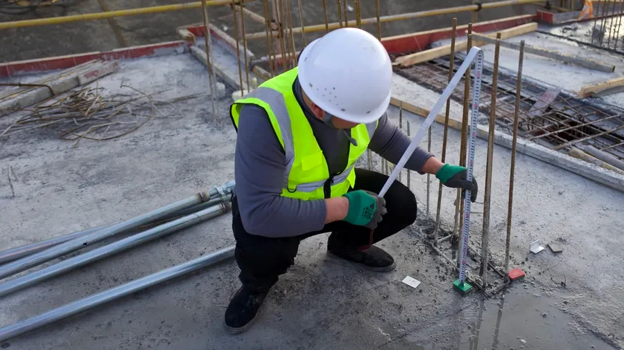
Snap layout lines on the base slab; verify and adjust pre-installed starter bars to align with the assembly cavity before the lift.

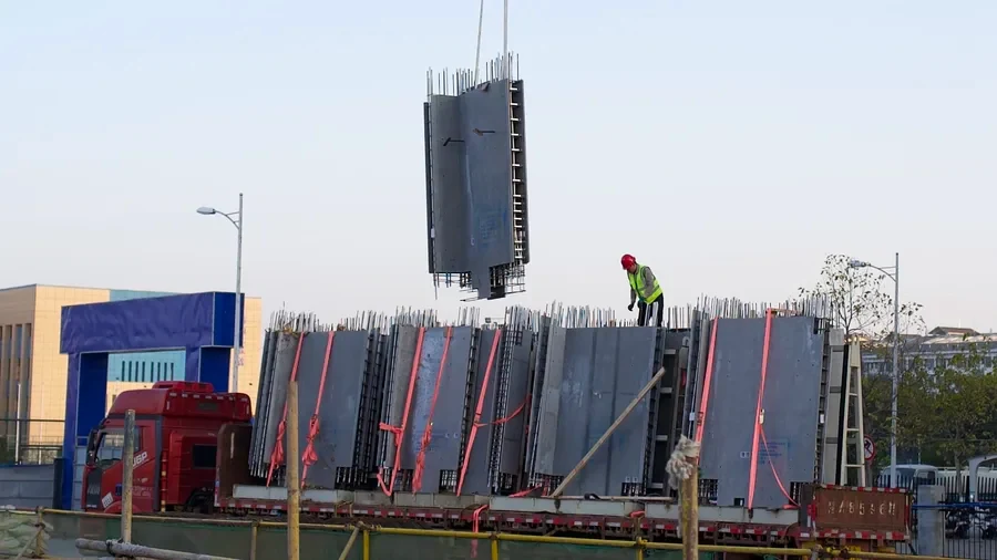
3 · Lift and place

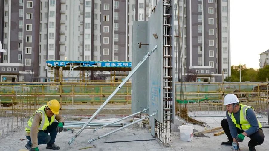
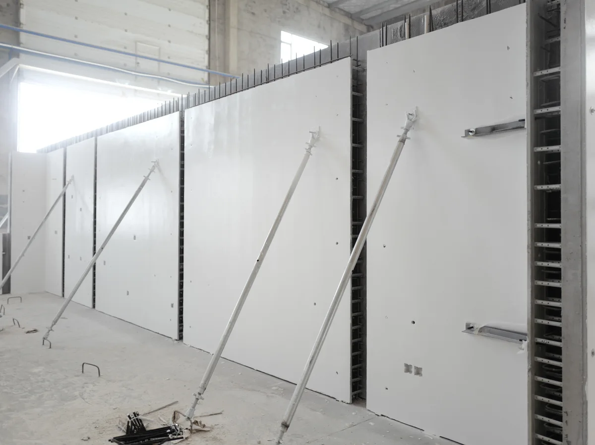
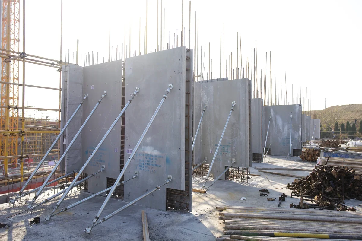
Standard light-duty crane, assembly under 1 tonne; a 3-person crew sets each shear wall in minutes, with four adjustable diagonal braces.

4 · Rebar connection

Rebar continuity through lap splicing or mechanical couplers, per project structural design and applicable code, depending on member type.

5 · Plumb and level

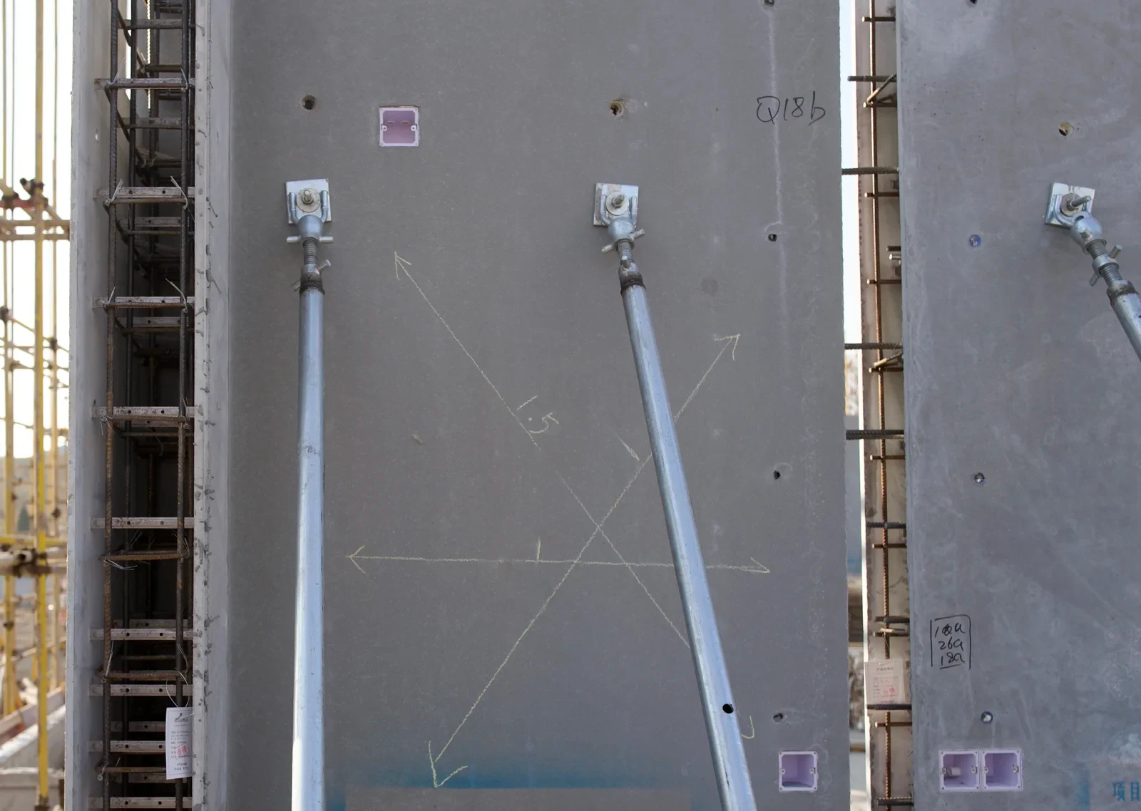
Adjustable diagonal braces align each assembly to vertical and horizontal tolerances; beams and slabs use temporary props, likewise removed after the pour.

6 · Base seal and preparation

Base mortar seal; venting and rebar positioning verified before concrete placement.

7 · Concrete placement

Project-specified structural concrete is placed and vibrated by conventional methods; pours above 3 m proceed in multiple lifts. Once cured, the core is monolithic cast-in-place, and the panel faces remain as the finish-ready substrate.

Assembly transport
Assembly transport
Assembly lifting
Assembly lifting
Rebar connection check
Rebar-connection check, starter or extended bars
Plumb, level, bracing
Plumb, level, and bracing
Adjacent horizontal rebar connection
Vertical rebar lap-splice and coupler details
Vertical lap-splice and coupler details
THE SEQUENCE, RENDERED

Ten moments from foundation to pour

The construction workflow is industrialized; the structural method is unchanged. From the ShellForm™ System installation model. Connection type, splice parameters, and joint schemes follow each project’s structural design and applicable code.

SEQUENCE 01 · FOUNDATION LEVEL

Excavation and base-slab casting come first; installation starts on the finished base. The base shown is illustrative: the same assemblies extend into foundations, strip footings, isolated footings, and continuous basement walls (see Below grade).

SEQUENCE 02 · PLACEMENT & COUPLERS

A wall member is lowered onto its starter bars; a worker torques the mechanical couplers at the base. Vertical bars connect by mechanical couplers or by lap splices, with the connection type and the associated reinforcement detailing per the structural design and the governing code; the footage shows the coupler method. Four adjustable braces plumb and hold each member, no scaffolding, and come off the day after the pour.

SEQUENCE 03 · JOINTS & SEALING

Between adjacent members, horizontal connection bars are tied on site at the joint; splice lengths and the associated reinforcement detailing follow the structural design and the governing code. The outer joint takes a PE backer rod and sealant; the inner gap closes with aluminum forms. The arrangement shown is one of several accepted schemes; joint methods differ in the site precision they demand, and the selection is matched to project conditions and crew capability, confirmed by the responsible structural engineer.

SEQUENCE 04 · SHAPED MEMBERS

Shaped members, T, L, corner, follow the same rule: vertical connections to the starter bars below, horizontal connections to each adjacent member. Shown: an integral corner assembly making both connections at once.

SEQUENCE 05 · COLUMNS

Columns follow the same rule: vertical bars connect by mechanical couplers or by lap splices; the coupler configuration is shown here.

SEQUENCE 06 · THE FLOOR, MEMBER BY MEMBER

Walls and columns are placed one after another across the floor. Hand-hole openings at splice points close with aluminum forms once connections are complete.

SEQUENCE 07 · BEAMS

Adjustable steel props are erected first. Beam assemblies are lowered level onto the props; top bars are threaded and tied on site, beam by beam.

SEQUENCE 08 · SLABS

Slab assemblies rest on point supports: adjustable props, not full shoring or scaffolding. Slab rebar is tied on site into beams and walls. Shown: the single-shell configuration; a wall-type slab configuration also exists.

SEQUENCE 09 · THE POUR

One pour, two views. Right: the whole floor cast monolithically, walls, beams, slabs, and columns together. Left: the same pour seen inside the wall, placed and vibrated like any cast-in-place pour.

SEQUENCE 10 · THE FULL CYCLE

All members set, cast, and cured; then the floor above begins. A 3-person crew; 3 to 4 days per floor, one cycle repeating upward.

SITE FOOTAGE · ASSEMBLY LIFT
SITE INSTALLATION

Watch an assembly go up

A hollow stay-in-place assembly is lifted into position, braced, and connected, with formwork function, ties, rebar, and embeds already inside. Complete procedures are documented in the ShellForm™ System technical video.

SITE FOOTAGE · ASSEMBLY TRANSPORT
SITE FOOTAGE · ASSEMBLY INSTALLATION
FACTORY · PRE-SHIPMENT TRIAL ASSEMBLY
LOGISTICS · CONTAINER LOADING · 41 UNITS
FIELD ADAPTABILITY & QUALITY INSPECTION

Modifiable on site, inspectable before and after the pour

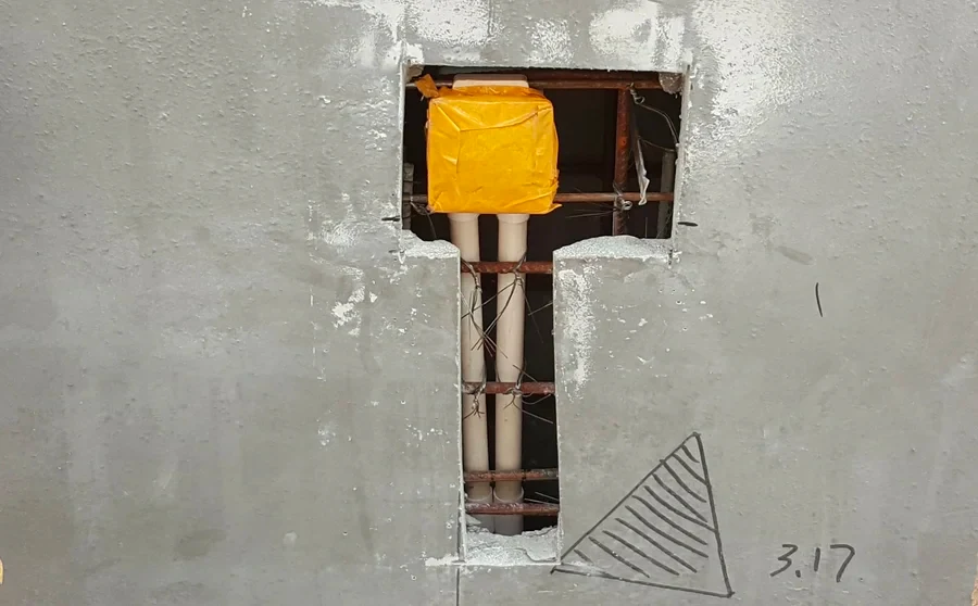
On-site adjustment for MEP changes
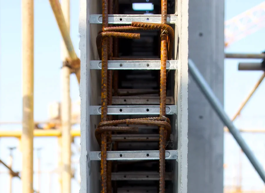
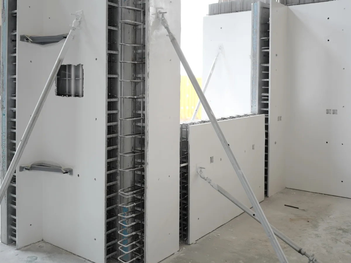
Open cavity before structural pour
Open cavity before the structural pour
Localized inspection opening

On-site modifiability

Non-structural panel faces can be locally modified for project design changes; for MEP changes the panels can be freely cut and patched by conventional methods, without altering the structural load path.

Pre-pour transparency

Open cavities keep reinforcement and embeds visible: bar specifications, spacing, and cover, lap splices or mechanical couplers, conduits and boxes, and insulation can all be inspected before the structural pour.

Post-pour inspection

Where required, the cast-in-place structure itself can be inspected and verified through infrared thermal imaging, core sampling, and localized panel opening, under applicable approval documents and engineer-of-record specifications.

No debonding, no delamination

Panel and core share the same cementitious chemistry, anchored by the dense connector grid; panels are inorganic and non-combustible.

INSPECTABLE BEFORE AND AFTER THE POUR
QUALITY · COMPONENT TRACEABILITY

Every component answers for itself

Every assembly leaves the factory with a QR identity tag. One scan resolves the component’s own record: what it is, where it belongs on the plan, and exactly what went into it.

SHELLFORM™ SYSTEM
2F-MKQ-••
L-shaped shear wall assembly
XPS insulation · 70 mm
European pilot project
Specimen QR code; scan to open the sample component record
SPECIMEN TAG · SCAN TO OPEN THE SAMPLE RECORD
Floor plan; the sample member highlighted in green
Floor plan: the sample member highlighted in green
Member detail: the sample member’s L-shaped section with panel faces, insulation, connectors, reinforcement cage, and rebar splice connections to adjacent members
Member detail in section: panel faces, insulation, connectors, reinforcement cage, and the rebar splice connections to adjacent members
Plan locationFloor 2F · highlighted in green
Reinforcement••.• kg
Cementitious panel material••• kg
Insulation board•.•
Steel connectors•• pcs
Insulation connectors•• pcs
Decorative finish•.•
Production QABatch and inspection data linked

Identity on every assembly

Each delivered assembly carries a QR tag tied to its component ID. The tag resolves to a live record: member type, dimensions, floor, and its highlighted position on the layout plan.

A bill of materials per component

The record carries the component’s own quantities: reinforcement, cementitious panel material, insulation board, steel and insulation connectors, and decorative finish. Material accounting is component-level, drawn from production data, rather than estimated across the pour.

Quality and conformity, attached

Production QA data links to the same record, and key inputs carry their own certificates: reinforcement mill certificates to the specified grade, CE documentation where the market requires it, tracked to batch and producer. Conformity documentation is added as evaluation programs complete. One scan, the component’s full story.

Low carbon, accounted for

The panel formulation incorporates 50 to 70% low-carbon constituents, and the permanent panels remove separate reusable formwork from the site. Because every component carries its own material record, material and embodied-carbon accounting can run at component level, and the same record structure is built to carry the documentation that follows. Reduced site waste, traceable materials, and trackable carbon data support LCA, EPD, and LEED documentation.

Specimen shown with masked identifiers and quantities; live records are issued per project. Deployed on the first European pilot project, now shipped and in transit.

DESIGN & ENGINEERING

Designed as cast-in-place. No parallel system design

ShellForm does not require its own structural design regime the way conventional precast does. The locally approved cast-in-place design is used as issued; assemblies are simply production divisions of that design, split by parameters every concrete code already defines.

CONVENTIONAL PRECAST

Every project is re-engineered into the precast regime

The structure is first redesigned under the local precast code: panel joints become structural connections, seismic equivalence is proven case by case, and the system locks in early design. The conversion repeats for every project and market.

SHELLFORM

The approved cast-in-place design is the only design

Assembly boundaries are production divisions, not structural joints; the monolithic load path is untouched. Split rules reduce to lap lengths, cover, and spacing, parameters every concrete code already defines, so the same engine ports across jurisdictions by loading the matching parameters, with no redesign loop between issued drawings and production. The system adds the delivery layer onto the issued design: cementitious composite panels, connectors, and embeds are generated by rule, and insulation follows the design’s own specification.

1

Approved structural drawings

The direct split input, taken as issued

2

Rule-based split

Numbered components; structure unchanged

3

Assembly detailing

Panels, connectors, and embeds configured per assembly

4

Production documents

Process-step drawings and bill of materials, generated per assembly

5

Factory production unit

Produced to specification, QR-traced to batches and QA records

WHERE THE SYSTEM LEADS

The tighter the delivery constraints,
the greater the value

Because the load-bearing structural path remains conventional cast-in-place reinforced concrete, applicability is driven less by building type than by project delivery conditions. Advantage concentrates where these press hardest, and compounds with each added floor.

Schedule

Repeatable site trades move into the factory, supporting fixed handover dates.

Labor scarcity

Reduced dependence on site trades where skilled labor is scarce.

Seismic acceptance

The cast-in-place core follows conventional RC code logic; delivered at scale in zones up to 0.30g.

Logistics and remote sites

Light hollow assemblies ease long-distance and constrained transport by standard truck.

Dense urban sites

Less laydown and site work, reducing traffic, noise, and dust pressure on tight sites.

Climate exposure

Factory-prepped assemblies reduce weather-exposed site work in rain, heat, and cold.

Scale and repetition

Repeatable layouts industrialize fastest; benefits compound with volume.

Sustainability

Reduced site waste, traceable materials, and trackable carbon data support LCA, EPD, and LEED documentation.

Most applicable to cast-in-place reinforced-concrete structures: walls, columns, beams and slabs, plus complex zones such as basements, cores, shafts, water tanks, utility tunnels, and isolated footings. Building scope: occupied building structures such as residential, hospitality, affordable housing, and public buildings.
Typically reduces
0%
structural-phase schedule, compressed versus conventional cast-in-place baselines
Reduces up to
0%
on-site labor hours for main structural works; in labor-constrained markets, read as structural-phase throughput gains for existing crews

Derived from delivered-project data; indicative ranges versus conventional cast-in-place baselines for main structural works. Outcomes vary by building type, height, local labor structure, assembly scope, and adoption scope. Validate project economics with local contractors.

COMPARED WITH OTHER APPROACHES

Deep factory integration, an unchanged cast-in-place code path, and open pre-pour inspection, together

Existing approaches face a fundamental trade-off: the deeper their factory integration, the further they move from conventional cast-in-place structural design and code. The ShellForm™ System resolves this trade-off.

FORMWORK ROUTES · TEMPORARY & NON-STRUCTURAL PERMANENT

Preserve the structure, stop at formwork

Timber, steel, and aluminum systems keep the cast-in-place structure but stop at the formwork step. Non-structural permanent formwork, such as ICF and panel-based systems, adds insulation or a panel face, but reinforcement and MEP remain site trades; the site stays a sequential multi-trade workflow.

STRUCTURAL PRECAST

Integrates more, becomes the structure

Structural stay-in-place and solid precast products integrate deeper, but the factory product becomes load-bearing: heavier logistics, joint design, and system-specific code acceptance.

VOLUMETRIC MODULAR

Deepest integration, furthest from convention

Whole-room modules carry the most factory content, with oversize logistics, heavy cranage, and system-specific approval frameworks.

SHELLFORM™ SYSTEM

Industrialized delivery, conventional structure

Deep factory integration while preserving the cast-in-place load path, standard reinforced-concrete code, and open pre-pour inspection.

Adoption friction is lowered for every stakeholder
Engineer · conventional RC designContractor · a leaner site workflow on the familiar pour-and-inspect basisPlan reviewer · standard RC code reviewInsurer · conventional risk basisOwner · conventional asset class and audit trail
EXTENDED EVALUATION MATRIX

Eight delivery systems, dimension by dimension

SCROLL HORIZONTALLY · FIRST COLUMN AND SHELLFORM COLUMN STAY FIXED →

POINT SOLUTIONS
site robotics, BIM tools
TEMPORARY FORMWORK
timber / steel / aluminum
3D PRINTED CONCRETENON-STRUCTURAL PERMANENT FORMWORK
ICF, PVC, fiber-cement
STRUCTURAL PERMANENT FORMWORK
twin-wall / semi-precast
SOLID PRECASTVOLUMETRIC MODULAR
PPVC / MiC
SHELLFORM™ SYSTEM
WHAT IT ISSingle-task site automationReusable site formworkLayer-extruded outer shells plus concrete coreFoam, polymer, or fiber-cement shutteringPrecast structural leaves plus lattice girders and a partial site-cast coreFactory-cast structurally complete elementWhole-room integrated moduleHollow stay-in-place assembly with factory-integrated trades
PRODUCT IS STRUCTURAL?No new structural productNo; CIP concrete is structuralSystem-dependentNo; site-cast core is structuralComposite / hybrid after site fillYes, designed as load-bearingYes, system-dependentNo; site-cast RC core is structural
CODE PATHWAYNo new wall system; existing project code appliesStandard CIP RC codeEmerging acceptance criteria; jurisdiction-specificRC wall design plus product-specific acceptanceComposite design, jurisdiction-specificPrecast structural design plus plant QASystem acceptance frameworks plus local RC codeStandard RC code; ICC-ES ESR and ETA in progress
SEISMIC PERFORMANCEUnchanged from baselineStructure is CIP itselfLimited high-seismic data; project-specificStructure is CIP itselfComposite behavior; joint detailing project-specificJoint-dependent; connection design criticalSystem-dependent; module connections criticalPreserves CIP load path; cyclic-test stiffness and capacity at or above equivalent CIP¹
FACTORY-INTEGRATED TRADESSingle trade, on-siteFormwork onlyWall geometry only; manual rebar; MEP and finishes on siteFormwork only, plus insulation for ICFFormwork plus partial reinforcementConcrete and rebar; joints and MEP on siteStructure, MEP, finishes, and fit-out, 7 to 10+ tradesFormwork, rebar cage, insulation, MEP rough-in, connectors, finish substrate, 6 to 8 trades
REBAR / MEP VISIBILITY BEFORE POURN/AOpen, no permanent productPartialInspectable before fill; constrained by closed formworkCavity only; precast leaves' rebar not field-verifiableClosed, factory-castClosed, factory-finishedOpen, inspectable cavity before site fill
PRODUCTION, CYCLE & EQUIPMENTEquipment and software; no component productionReusable forms; site support, pour, strippingOn- or near-site robotic printer; proprietary mix; manual rebarFactory-molded components; site stack, rebar, and fillPrecast leaves on line; flip and cure; site propping and fillProject or standard molds; factory casting, curing, storage; crane erectionModule line plus finishing stations and storage yard; multi-cycle, heavy liftFactory-integrated wet-state assembly; offline-prepared assembly fixture mounted on line
ELEMENT SCOPESingle step within existing workflowAny element; site-builtPrimarily wallsWalls, and columns for PVC systemsWalls; lattice-girder slabsWalls, slabs, beams, columns, stairs on dedicated linesWhole rooms; repetitive layoutsWalls, columns, beams, slabs, L/T configurations
UNIT WEIGHT & TRANSPORTEquipment deliveryStandard equipment delivery; reusableEquipment delivery; structure built on siteLight hand-installed components; standard truckCrane-lifted precast panels; radius project-specific~3 to 5 t per 3 × 3 m wall; crane erection; radius project-specificConcrete modules ~25 to 30 t; high-capacity crane; oversize logistics~0.8 to 1.0 t per 3 × 3 m wall pre-fill; standard truck and crane; radius ~500 to 1,000 km¹
SITE LABOR & FLOOR CYCLESingle trade; site labor unchangedMulti-trade sequential site work; weather-dependentSmall printer crew; reinforcement and MEP trades on siteMulti-trade; site rebar and fill crewsLifting crew plus cavity rebar and fill; 3 to 4 days per floor¹Lifting, connection, and grouting crews; 4 to 6 days per floor¹Module lift, connection, and interface trades; multi-cycle3-person lift crew; limited on-site splicing and hand-hole patching; 3 to 4 days per floor¹
FAULT TOLERANCE & REPAIRABILITYTolerant; no new permanent productTolerant; rework before pourLimited; printed geometry hard to modify after cureTolerant for chases; concrete repair as standardLimited at leaf joints; precast tolerance criticalLimited; structural panels not field-modifiableVery limited; module changes difficult on siteTolerant; panel face is field-cut and chased like a standard wall
KEY CONSTRAINTOne step only; site workflow otherwise unchangedSequential site trades plus weather dependencyWall-centric scope plus manual reinforcement; largely low and mid-rise in practiceCost premium versus CIP in low-labor markets; jurisdiction-specific code pathsFactory precast process plus crane lift and joint detailingProject molds plus heavy weight; joint-dependent; short transport radiusOversize logistics, heavy crane, and factory capex; short transport radiusMarket-by-market evaluation pathways, qualified partner-plant coverage, and local ecosystem build-out

¹ Ranges are directional and project-specific by geometry, design, crew organization, crane availability, and jurisdiction. ShellForm stiffness and capacity figures from program-level quasi-static cyclic testing, with panel contribution conservatively excluded in structural design; labor and transport figures from origin-market standard reference data and delivered-project benchmarks. Comparison reflects typical implementations; specific products vary.

PROJECTS

A decade of delivered projects across structural types, transport distances, and seismic zones

Hilton Hotel, Shanghai

Hilton Hotel

Shanghai · Hospitality

Lakeville Phase 3, Shanghai

Lakeville Phase 3

Shanghai · Luxury residential

Faculty housing, Nanchang

Faculty Housing

Nanchang · Residential, supply completed 2026

PROJECT TYPESTRUCTURE · HEIGHTLOCATIONTRANSPORTSEISMICYEARSHELLFORM PRODUCTSDELIVERY
Premium residentialShear wall · 4F · 14.4 mShanghai~150 km0.10g2016Shear wall, infill wall, beamOwned factory
Premium residentialShear wall · 6F · 21.3 mShanghai~150 km0.10g2019Shear wall, beamOwned factory
Public buildingFrame · 4F · 16.5 mShanghai~200 km0.05g2019Column, beamOwned factory
Commercial rental apartmentFrame-shear · 14F · 45.3 mShanghai~750 km0.10g2020Extra-thick shear wall, 540 mmOwned factory
High-rise residentialShear wall · 18F · 57 mNanchang~10 km0.05g2021Extra-tall shear wall, 4,500 mmOwned factory
High-rise residentialShear wall · 24F · 72 mFoshan~800 km0.10g2021Column, basementOwned factory
HospitalityFrame-shear · 12F · 45.4 mShanghai~750 km0.10g2021Extra-thick shear wall, 540 mmOwned factory
Affordable housingShear wall · 27F · 81 mHainan~30 km0.30g2023Shear wall, boundary elementPartner factory
Faculty housingShear wall · 18F · 60 mNanchang<10 km0.05g2026L-shaped shear wall, boundary elementOwned factory
Detached villaShear wall · 3F + basement · 10 mEurope~16,000 km<0.04g2026Insulated wall, beam, slab, columnOwned factory

Sources: internal project records; additional counterparty identities not disclosed. Owned and partner factories have each delivered multiple projects under the ShellForm framework; the above is a representative selection.

PROOF

Ten years of field deployment. One million square meters delivered

0+
m² delivered across building types and high-seismic zones
0+
patents and applications across the full value chain
Industry standard
co-authored the governing technical standard for the system in its market of origin, 2018
First Prize
Jianhua Award 2021, evaluated by a 34-academician jury
2014

Foundational R&D launched

2018

Governing industry standard for the system published

2021

Jianhua Award First Prize

2023

Licensing model launched; partner-factory delivery begins

2026

ShellForm Technologies Inc. founded in the US as the global technology company for the system, holding its international IP, brand, and certification programs; ICC-ES evaluation and European ETA route in progress; first European pilot shipped, in transit by sea

HOW WE WORK

ShellForm supplies the proprietary core; partners operate and scale locally

Repeatable site work, productized: the structural core stays project-specific and local, while the delivery layer behind it is standardized, produced, and priced as a product system.

01 · WHO WE SERVE

Four stakeholders, one delivery system

Project sponsors and owners

WHO
Developers, public agencies, industrial and hyperscale owners
NEEDS
Delivery certainty, opening and operating dates, budget control, ESG documentation
SHELLFORM ROLE
Delivered-project proof, less site work, and traceable material and carbon data

Delivery decision-makers

WHO
GCs, EPCs, design-build firms, strategic contractors
NEEDS
Labor shortage, site congestion, weather exposure, trade coordination
SHELLFORM ROLE
Factory-integrated assemblies reduce trade interfaces on site while preserving cast-in-place RC structural design

Specifiers and approval stakeholders

WHO
Structural engineers, architects, AHJs, certifiers, testing labs, insurers
NEEDS
Clear code path, structural safety, evidence, inspectability, and traceability
SHELLFORM ROLE
Preserves the cast-in-place RC code path, with added evaluation, quality-control program, and traceability

Local production and delivery partners

WHO
Component factories, contractors with plants, JV partners, and other local production partners
NEEDS
Project pipeline, capacity utilization, differentiated capability
SHELLFORM ROLE
Licensed production with assembly fixtures, equipment, proprietary inputs, software, quality-control program, and brand-use rights
02 · WHO RUNS WHAT

The delivery ecosystem

ShellForm operates 1 and 2; partners and local supply operate 3 to 5

Data backbone: quantities are known by design; panel materials, connectors, and the cast concrete volume all trace to each component’s geometry and production record

1SHELLFORM

Design & data

System rules, production data, software

2SHELLFORM

Material & equipment supply

Proprietary materials, qualified supply base

3PARTNER

Authorized production & regional stock

Partner facilities produce under ShellForm™ spec; in-market stock configured to order

4LOCAL SUPPLY

Local ready-mix

Concrete from local batch plants

5PARTNER

Site execution

Local contractor places, connects, pours

SHELLFORM PROVIDES

System design

Design standards and system rules, component splitting rules, digital tools and production data

Materials and equipment

Proprietary cementitious composites, connectors, and special parts; assembly fixture sets, ShellForm-owned and leased; equipment supplied or approved

Governance and support

Partner qualification and the quality-control program, certification and evaluation coordination, training, audits, and data compliance

LOCAL PARTNERS OPERATE

Market interface

Customer and contractor relationships, local permitting and approvals, regional stock and order configuration

Production operations

Authorized assembly production to ShellForm technical requirements, and factory-to-site logistics

Project delivery

Site coordination and installation, locally sourced ready-mix concrete and reinforcement, inspection and acceptance support

03 · THE PRODUCT MODEL

Stockable by design, applied where it fits

Load-bearing prefabrication cannot hold inventory; hollow, non-structural units can. The system makes stock possible for a category that never had it. Where scopes are standardized and repetitive, stock applies; elsewhere, members are produced to project design.

WHY PREFAB CANNOT STOCK

Load-bearing prefabrication cannot be inventoried

In conventional prefabrication every factory unit is structure itself, engineered for a single project; elements cannot be cut, recombined, or reassigned, and cannot be held as general, reusable stock.

WHY SHELLFORM CAN STOCK

Hollow, non-structural standard units can be cut and reconfigured

ShellForm™ assemblies are hollow shells that carry no structural load; the load-bearing structure is formed on site. The factory-integrated cage uses distributed reinforcement standardized per unit length, so units can be cut and recombined within defined rules, with cut lines clear of connectors, without changing the structural basis.

How stock becomes delivery: corners set the shape; straights set the length

The stock model applies to standardized, repetitive scopes; project-specific members and engineered geometries are produced to project design, not from stock.

Corners set the shape. L- and T-corner assemblies are supplied standard and never cut.

Straights set the length. Straights are mass-produced in modular dimensions and installed at full length, with only the last closing unit of each wall cut to the remaining dimension.

Pre-formed positions. Standard units carry pre-formed lifting, bracing, and conduit and box positions.

Configured at regional points. Some are stocked without pre-set openings and configured to project design at regional processing points.

CORNERS SET THE SHAPE · STRAIGHTS SET THE LENGTH
04 · THE COST AND PRICING LOGIC

Restructures structural-phase cost, not line-item prices

Cost items are removed from site scope, shifted into the factory, added as system costs, or left unchanged by design. Fewer site operations and coordination interfaces lower site-management burden and overheads; factory QA reduces rework and tolerance variance.

REMOVED FROM SITE
SHIFTED TO FACTORY
ADDED AS SYSTEM COSTS
UNCHANGED BY DESIGN

Removable formwork

Panels become the permanent face

Reinforcement cage assembly

Pre-assembled, delivered ready to pour

Proprietary materials

Composite panels, connectors, rebar spacers

Site-cast monolithic RC core

Load path 100% cast-in-place

Formwork-dedicated scaffolding

Not needed in the shell phase

Insulation system

Set and anchored in the factory

Factory production capacity

Fixtures, equipment, and labor amortized

Reinforcement design and splicing

Per structural design and code

Rough plastering and substrate prep

Panel face is a finish-ready substrate

MEP embedment coordination

Conduits, boxes, and embeds pre-placed

Certification and evaluation pathway

Market conformity, by market

EOR design authority

Engineer of record retains authorship

On-site insulation installation

Eliminated from the site sequence

Coatings and decorative finish layers

Factory-applied per project scope

Unit-level traceability

QR-linked to material and QA records

Permit and inspection processes

Via conventional code pathways

SHELLFORM’S COMMERCIAL SCOPE

Prices the system supply, not the project’s all-in per-m² cost

Product families and technical standards
ShellForm supplies a product system, not GC services
Component-supply pricing
Direct from ShellForm at entry; local partner factories at scale
Owners specify the ShellForm™ System
GCs then price it into the project bid
Project per-m² cost
Covers GC execution, local labor, installation, logistics, MEP, finishes, and integration, beyond ShellForm’s supply scope
PER-M² COST LOGIC

Not a fixed catalogue rate; shaped by system fit and project conditions

System fit
Which members, locations, and factory-integrated scope ShellForm covers
Project conditions
Scale, location, transport, local labor, code, design, and finish scope

Qualitative framework. Specific unit economics vary by market, scope, and partnership tier.

05 · FROM PROOF TO SCALE

Direct supply and regional stock create the market foundation for qualified production capacity

MODE A · MARKET SEEDING · prove demand, approval pathways, partner execution, and stock turnover
Direct supply

ShellForm-supplied assemblies support first projects, references, and approval pathways; early market entry proceeds without committed plant investment.

STATUS · First international pilot shipped, in transit
Regional stock

Market partners hold and configure territory inventory, building customer access and repeatable demand; stock turnover becomes the demand signal for capacity.

STATUS · Regional partners in development; European inventory model in preparation
MODE B · QUALIFIED PRODUCTION CAPACITY · capacity follows proven demand and market economics
Expanded qualified supply base

Additional ShellForm-qualified capacity, including expanded supply from the established production base, where logistics and economics support the market.

Existing-plant retrofit

Operating component factories add a ShellForm-qualified product line; plant and operations investment remains with the partner.

Greenfield regional facility

New dedicated capacity, located where market volume, logistics, and regional coverage justify dedicated investment.

Underutilized-capacity conversion

Underutilized industrial assets transformed into ShellForm-qualified production at lower capital cost.

Commercial architecture: both modes operate under one licensing and certification framework

Brand-use license, factory qualification, quality-control program, certification listing, proprietary material and equipment supply, assembly fixture leasing, software and data reporting, and audit; territory, stocking, and production rights are granted separately, staged with market development.

Partner capital builds market capacity; ShellForm capital builds the system

IP, certifications, core technology, and data. Ordinary ready-mix concrete, reinforcement, and commodity materials stay local by design. Evaluations and certifications are held by ShellForm Technologies, and qualified partner factories produce as listed locations under them.

One technical basis, market-by-market pathways
1

Technical evidence basis · held by ShellForm Technologies

Test data, engineering analysis, and the factory QA backbone form one evidence base; one coordinated multi-standard test campaign feeds all target markets.

2

Market conformity document · the same basis, converted per market

The same evidence base converts into each market's conformity document; ShellForm Technologies Inc. is the report holder in each pathway, and partner factories are listed locations under it.

3

Factory audit regime · one QA backbone, plant-by-plant audits

Plants join by audit, not re-testing; once qualified, a partner plant is added to the reports as a listed location, and the technical file remains the holder's property. Where no formal product-evaluation pathway exists, the ShellForm™ enterprise standard governs quality and traceability.

WHERE WE ARE

Certification underway in three markets. First international pilot shipped, in transit

IN PROGRESS

US ICC-ES ESR and Australia NCC pathway

Product evaluation underway under the relevant US and Australian pathways

IN PROGRESS

European ETA route

Advancing the ETA route with European Technical Assessment Bodies, coordinated with the first international pilot

SHIPPED · IN TRANSIT

First international pilot, Europe

Components produced and shipped, in transit by sea for the first European pilot project

IN DEVELOPMENT

Assembly module software, Phase 1

Design-to-production software for assembly splitting, BOM, and project data on the ShellForm™ System

HOW TO ENGAGE

Built to industrialize cast-in-place concrete construction worldwide

STRATEGIC INVESTORS

Capital to accelerate certification and overseas market expansion.

PROJECT OWNERS AND DEVELOPERS

Owners, developers, and GCs seeking faster, industrialized delivery on the conventional code path.

TERRITORY AND CAPACITY PARTNERS

Regional market-makers, stock partners, and qualified capacity partners under the ShellForm pathway.

SOFTWARE AND PLATFORM PARTNERS

Teams building digital tools on the ShellForm™ System as a base layer.

Or directly: hao@shellformtech.com · LinkedIn